- 您现在的位置:买卖IC网 > Sheet目录337 > LT3597EUHG#PBF (Linear Technology)IC LED DRIVER TRPL STP DWN 52QFN
LT3597
APPLICATIONS INFORMATION
LED Current Dimming
Two different types of dimming control are available with
the LT3597. The LED current can be dimmed using the
CTRL1-3 pin or the PWM1-3 pin.
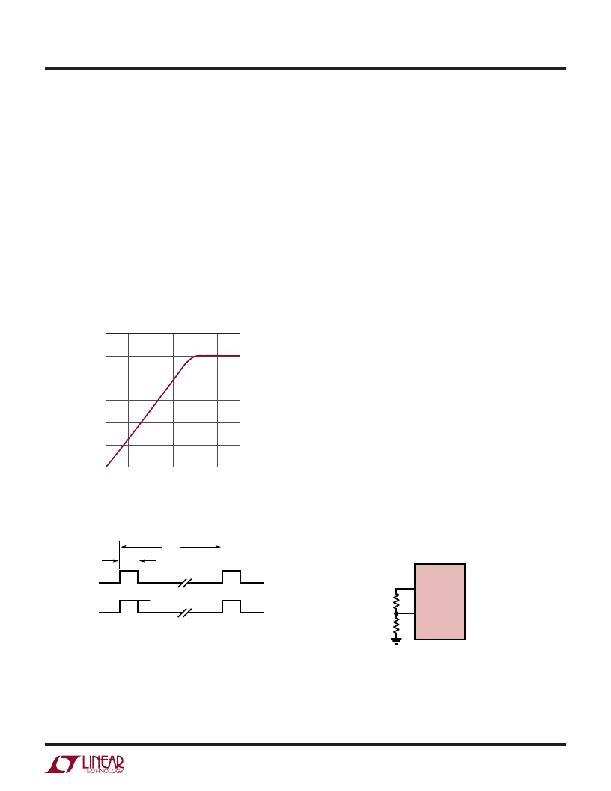
For some applications, a variable DC voltage that adjusts
the LED current is the preferred method for brightness
control. In that case, the CTRL1-3 pin can be modulated
to set the LED dimming (see Figure 4). As the CTRL1-3 pin
voltage rises from 0V to 1.0V, the LED current increases
from 0mA to the maximum programmed LED current in a
linear fashion. As the CTRL1-3 pin continues to increase
past 1.0V, the maximum programmed LED current is
maintained. If this type of dimming control is not desired,
the CTRL1-3 pin can be tied to V REF .
120
100
80
60
40
20
0
0 0.25 0.5 0.75 1 1.25 1.5
CTRL1-3 (V)
3597 F04
Figure 4. LED Current vs CTRL1-3 Voltage
t PWM
For True Color PWM dimming, the LT3597 provides up to
10,000:1 PWM dimming range at 100Hz. This is achieved
by allowing the duty cycle of the PWM1-3 pin to be reduced
from 100% to 0.01% for a PWM frequency of 100Hz (see
Figure 5), hence a minimum on-time of 1μs and a maxi-
mum period of 100ms. PWM duty cycle dimming allows
for constant LED color to be maintained over the entire
dimming range.
Using the T SET Pin for Thermal Protection
The LT3597 contains a special programmable thermal
regulation loop that limits the internal junction tempera-
ture. This thermal regulation feature provides important
protection at high ambient temperatures, and allows a
given application to be optimized for typical, not worst-
case, ambient temperatures with the assurance that the
LT3597 will automatically protect itself and the LED strings
under worst-case conditions.
As the ambient temperature increases, so does the internal
junction temperature of the part. Once the programmed
maximum junction temperature is reached, the LT3597
linearly reduces the LED current, as needed, to maintain
this junction temperature. This can only be achieved when
the ambient temperature stays below the maximum pro-
grammed junction temperature. If the ambient temperature
continues to rise above the programmed maximum junc-
tion temperature, the LED current will reduce to less than
20% of the full current.
A resistor divider from the V REF pin programs the maximum
part junction temperature as shown in Figure 6.
t ON(PWM)
LT3597
PWM1-3
V REF
LED1-3
CURRENT
MAX I LED
R2
T SET
3597 F06
Figure 5. LED Current Using PWM Dimming
R1
3597 F07
Figure 6. Programming the T SET Pin
3597fa
13
发布紧急采购,3分钟左右您将得到回复。
相关PDF资料
LT3598IUF#PBF
IC LED DRIVR WHITE BCKLGT 24-QFN
LT3599IFE#PBF
IC LED DRVR WHITE BCKLGT 28TSSOP
LT3743EFE#PBF
IC LED DVR HP CONST CURR 28TSSOP
LT3745IUJ#TRPBF
IC LED DVR 16CH 50MA 40QFN
LT3746IUHH#TRPBF
IC LED DRIVER 32CHANNEL 56-QFN
LT3754IUH#TRPBF
IC LED DVR 16CH 50MA 32QFN
LT3755EMSE#PBF
IC LED DRVR HP CONS CURR 16-MSOP
LT3760EFE#PBF
IC LED DVR WHT/CLR BCKLT 28TSSOP
相关代理商/技术参数
LT3597EUHG#TRPBF
功能描述:IC LED DRIVER 60V TRIPLE 52-QFN RoHS:是 类别:集成电路 (IC) >> PMIC - LED 驱动器 系列:- 标准包装:6,000 系列:- 恒定电流:- 恒定电压:- 拓扑:开路漏极,PWM 输出数:4 内部驱动器:是 类型 - 主要:LED 闪烁器 类型 - 次要:- 频率:400kHz 电源电压:2.3 V ~ 5.5 V 输出电压:- 安装类型:表面贴装 封装/外壳:8-VFDFN 裸露焊盘 供应商设备封装:8-HVSON 包装:带卷 (TR) 工作温度:-40°C ~ 85°C 其它名称:935286881118PCA9553TK/02-TPCA9553TK/02-T-ND
LT3597IUHG#PBF
功能描述:IC LED DRIVER 60V TRIPLE 52-QFN RoHS:是 类别:集成电路 (IC) >> PMIC - LED 驱动器 系列:- 标准包装:6,000 系列:- 恒定电流:- 恒定电压:- 拓扑:开路漏极,PWM 输出数:4 内部驱动器:是 类型 - 主要:LED 闪烁器 类型 - 次要:- 频率:400kHz 电源电压:2.3 V ~ 5.5 V 输出电压:- 安装类型:表面贴装 封装/外壳:8-VFDFN 裸露焊盘 供应商设备封装:8-HVSON 包装:带卷 (TR) 工作温度:-40°C ~ 85°C 其它名称:935286881118PCA9553TK/02-TPCA9553TK/02-T-ND
LT3597IUHG#TRPBF
功能描述:IC LED DRIVER 60V TRIPLE 52-QFN RoHS:是 类别:集成电路 (IC) >> PMIC - LED 驱动器 系列:- 标准包装:6,000 系列:- 恒定电流:- 恒定电压:- 拓扑:开路漏极,PWM 输出数:4 内部驱动器:是 类型 - 主要:LED 闪烁器 类型 - 次要:- 频率:400kHz 电源电压:2.3 V ~ 5.5 V 输出电压:- 安装类型:表面贴装 封装/外壳:8-VFDFN 裸露焊盘 供应商设备封装:8-HVSON 包装:带卷 (TR) 工作温度:-40°C ~ 85°C 其它名称:935286881118PCA9553TK/02-TPCA9553TK/02-T-ND
LT3598
制造商:LINER 制造商全称:Linear Technology 功能描述:60V Triple Step-Down LED Driver Programmable Temperature Protection
LT3598_1
制造商:LINER 制造商全称:Linear Technology 功能描述:6-String 30mA LED Driver with 1.5% Current Matching
LT3598EFE#PBF
功能描述:IC LED DRVR WHITE BCKLGT 24TSSOP RoHS:是 类别:集成电路 (IC) >> PMIC - LED 驱动器 系列:- 标准包装:6,000 系列:- 恒定电流:- 恒定电压:- 拓扑:开路漏极,PWM 输出数:4 内部驱动器:是 类型 - 主要:LED 闪烁器 类型 - 次要:- 频率:400kHz 电源电压:2.3 V ~ 5.5 V 输出电压:- 安装类型:表面贴装 封装/外壳:8-VFDFN 裸露焊盘 供应商设备封装:8-HVSON 包装:带卷 (TR) 工作温度:-40°C ~ 85°C 其它名称:935286881118PCA9553TK/02-TPCA9553TK/02-T-ND
LT3598EFE#PBF
制造商:Linear Technology 功能描述:LED DRIVER BOOST PWM 2.5MHZ 制造商:Linear Technology 功能描述:LED DRIVER, BOOST, PWM, 2.5MHZ, TSSOP-24
LT3598EFE#TRPBF
功能描述:IC LED DRVR WHITE BCKLGT 24TSSOP RoHS:是 类别:集成电路 (IC) >> PMIC - LED 驱动器 系列:- 标准包装:6,000 系列:- 恒定电流:- 恒定电压:- 拓扑:开路漏极,PWM 输出数:4 内部驱动器:是 类型 - 主要:LED 闪烁器 类型 - 次要:- 频率:400kHz 电源电压:2.3 V ~ 5.5 V 输出电压:- 安装类型:表面贴装 封装/外壳:8-VFDFN 裸露焊盘 供应商设备封装:8-HVSON 包装:带卷 (TR) 工作温度:-40°C ~ 85°C 其它名称:935286881118PCA9553TK/02-TPCA9553TK/02-T-ND
